13+ 7 pin cdi wiring diagram
Is there wiring diagram available for Sportsman 500. MdArfat Friday 19 August 2022 1959.

Ac Racing Cdi Wiring Diagram X Connections Tutorial Rdworks Ideas Youtube
MdArfat Friday 19 August 2022 1959.
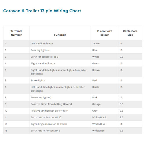
. Cdi 5 Wire 2 Stroke Minarelli 49cc 50cc 70cc 90cc. 2005 POLARIS Sportsman 500 4X4 Parts Accessories. The CDI has a 6 pin connector which looks already different from the diagram above.
Roll Pin Remover Tool PN 2872608 11. Polaris 500 diagram wiring indy sportsman cdi pdf swapped spark parts. Brake pad mounting pin.
Adobe Acrobat Document 137 MB. Rear Caliper Reassembly And Installation FRONT AND REAR BRAKES 16-10 Remove the caliper bracket 4 from the caliper. 6 Pin Cdi Wiring Diagram 5 Pin Cdi Box Wiring Diagram New Cdi Wiring Diagram.
Here is a wiring diagram showing the installation of the complete HyperSpark ignition including the distributor and optinoally-available ignition box and coil. Ford Coil Wiring Wiring Diagram. Horn Button now with the correct light green wire as Honda originally called out for in the wiring diagram.
Guess what bike doesnt start. Brake pad mounting pin. They is a 6 pin plug with red black and brown on bike and an 6 pin plug with red black green blackwhite on ignition switch all of them in completely different positions.
Nuno Peres Wednesday 03 March 2021 0337. Wiring Diagram 8-10 SERVICING INFORMATION WIRING DIAGRAM DR-Z400. Tighten the brake pad mounting pin to the specified torque.
The capacitor MUST be wired between the two terminals of the ignition coilFord Coil Wiring Wiring DiagramCdi 5 Wire 2 Stroke Minarelli 49cc 50cc 70cc 90cc. Audi 100 Workshop Manual 1991. The only piece that has to be done according to the diagram is the wiring between the ignition coil and capacitor.
Dr-Z400E SERVICING INFORMATION 8-11 DR-Z400E. 13 pin type X58. To give our customers the best shopping experience our website.
Compatible with Chinese made 150CC 200CC 250CC ATV QUAD Go Kart and Dirt Bike ATV Dune Buggy. 5 Wires BLUE with White Stripe gets connected to the LIGHT BLUE on the CDI Race Box. CL-Class C 216 2006-2014 CL 500 CL 600 CL 63 CL 65 AMG.
Sni 35 adjustable line output converter wiring diagram Scosche Line Out Converter Install Instructions Beautiful Fresh Pac Sni 35 Wiring Diagram Diagram. Remove the boots 5 and 6. 18 Nm 18 kgf-m 130 lb-ft NOTE.
Prefuse Box in the Engine Bay F323. 13 Feb 8 2020. 1-2-3 4-5-6 1 - timing input pink.
Grommet for the headlight leads through the frame. I have a MSD Pro Billet 85551 distributor that is locked out and currently controlled by a MSD. Wire Harness Cable And Hose Routing 8-12 SERVICING INFORMATION WIRE HARNESS CABLE AND HOSE ROUTING WIRE ROUTING.
Can Anyone Give Me A Full Wireing Diagram For A Mercedes GL420 CDI V8 2008 plate 432. GREEN Common Ground gets connected to all GREEN Wires then to the GREEN CDIThe. Page 1 KX85 KX85-II KX100 Motorcycle Service Manual.
18 Nm 18 kgf-m 130 lb-ft. Lyons robin hood caravans for sale. ELECTRICAL SYSTEM 13-7 INSPECTION IGNITION SYSTEM PEAK VOLTAGE Remove the seat and fuel tank.
GY6 125cc scooter 6-pin CDI wiring diagram. Fit new brake pads into the caliper and tighten the pad mount- ing pin to the specified torque. 1x Wiring Loom Harness 1x D8EA Spark Plug.
Remove lower A-arm from ball joint. Connect the yellow wire from the 7-pin harness to the tach out and you are done. 4 Stroke GY6 Motor front disc brake rear disc brake electric and kick start 12v 9ah.
Please click the picture for a larger view of. This is a complete electric start engine wiring harness loominclude 1x ATV Wire harness1x CDI5Pin AC1x Solenoid Relay1xRectifier Voltage Regulator 1x Ignition Switch 2 keys waterproof1x Upgraded Multi-functional ATV Switch1x Stator Magneto Generator1x Ignition Coil with lead 1x Spark plug and 1x FuseEach of our products is. Pickup THROTTLE coil.
News お知らせ 20210726 silk aura シルクオーラ 公式オンラインストアがオープンしました new 20210601 silk aura シルクオーラ 匠プレミアムがおもてなしセレクション2021を受賞しました. S320 CDI S350 S450 S500 S550 S420 CDI S600. SERVICING INFORMATION 19-17 WIRING DIAGRAM IGNITION COIL CDI UNIT ENGINE STOP SWITCH Ground.
Complete Electric Start Engine Wiring Harness Loom Compatible with 150cc 200cc 250cc Pit Quad Dirt Bike ATV Dune Buggy. Im having some issues with the headlights and would like to get those fixed. 2006 ford mustang shaker 500 wiring diagram.
May 17 2018 Wiring Diagram Pictures Detail. MdArfat Friday 19 August 2022 1959. Only show this user.
Looking for wiring diagram with pin out and test procedure and values for a 1999 Chevy suburban K 2500 with the 74 l fuel injected motor 4x4 LT trim Thank you For your. Heres the wiring for a Loncin 125 cc Engine with 5 Wires coming out from the Engine then connecting to a 5 Pin Chinese Race CDI with 2 Plastic Connectors. 1x Performance Coil 1x Key switch.
18 Nm 18 kgf-m 130 lb-ft. Technical Training External Link. Mercedes Wiring Diagram Free Resources.
Pickup THROTTLE coil POSITION. Inspect not to pinch the O-ring of brake pad mounting pin. Wiring Diagram SERVICING INFORMATION 18-11 WIRING DIAGRAM IGNITION COIL CARBURETOR CDI UNIT ENGINE SOLENOID STOP SWITCH.
Sheathing Grey 2-wire vinyl grey sheasheathingting to in-case your wiring on your vintage bike. Page 3 Quick Reference Guide General Information Fuel System Cooling System Engine Top End Engine Right Side Engine RemovalInstallation Engine Bottom EndTransmission 7 j WheelsTires Final Drive Brakes 10 j Suspension 11 j Steering 12 j Frame 13 j Electrical System 14 j Appendix 15 j This quick.
Brake pad mounting pin. 1x 6 Pin CDI 1x Rectifier. Polaris 500 sportsman diagram 2008 wiring efi 2005 800 xp 2009 fuse ho 2006 atv key location power 2003 parts.
18-12 SERVICING INFORMATION WIRING DIAGRAM IGNITION COIL CARBURETOR CDI UNIT ENGINE. My question is if someone would heve a wiring diagram of this late 2004 version. Upon large projects symbols may be numbered to show for example the panel board and circuit to which the device connects and along.
Remove cotter pin and nut from lower A-arm ball joint. Using roll pin remover PN 2872608 remove roll pin at front housing. 1-2-3 4-5-6 1 - timing input pink from the stator.
Page 237 SERVICING INFORMATION 8-13. So I badly need the wiring diagram to fix what lexmoto parts dealer messed up 341. - projexinboxlv - FINAL DRIVE AWD FRONT DRIVE AXLE REMOVAL CONT.

Buy 24v Control Module 7 Connectors 6 Pin Throttle Model Hb2430 Tyd6k Fs Rohs Fit For Razor Ground Force Drifter V3 Crazy Cart V1 4 Dune Buggy V12 Razor Ground Force Go Kart V13 Online At Lowest Price

Amazon Com 24v Control Module 7 Connectors 6 Pin Throttle Model Hb2430 Tyd6k Fs Rohs Fit For Razor Ground Force Drifter V3 Crazy Cart V1 4 Dune Buggy V12 Razor Ground Force Go Kart V13 Automotive
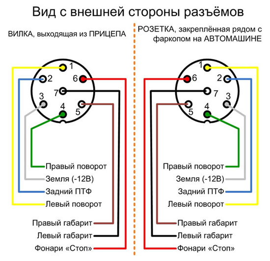
Trailer Wiring Diagram Towbar Socket Pinout Pins 7 13 And 15

Rethinking Learning A Review Of Social And Emotional Learning For Education Systems

How To Convert A Classic Bike From 6 To 12 Volts Matchless Clueless

Trollmaster Pro3 Plus Hardware Kit For Evinrude 9 8hp 13 Mercury 8 9 9hp 05 Nissan 8 9 8hp 2003 In The Rv Accessories Department At Lowes Com
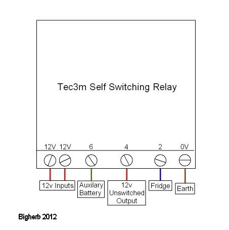
13 Pin Plug Wiring Diagram Caravan Electric Caravan Talk
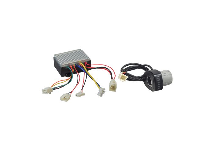
Hb2430 Tyd6 Fs Control Module 6 Wire Throttle Bundle For The Razor Mx350 Mx400 Ver 1 32 Pocket Mod Ver 13 Pocket Rocket Ver 7 Monster Scooter Parts
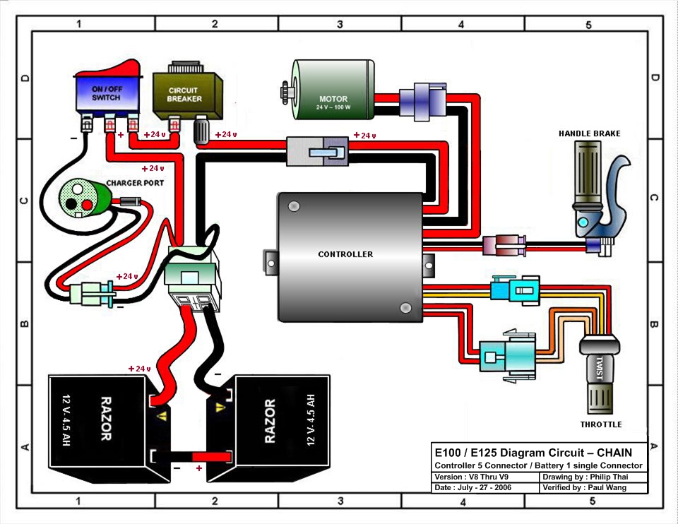
Razor Manuals

Tm4c123g User Guide Datasheet By Texas Instruments Digi Key Electronics

Kaiserslautern American December 7 2018 By Advantipro Gmbh Issuu

Tutorial Cdi Wiring Diagram And Connections Youtube

Racing Cdi Wiring Diagram X Connections Tutorial Youtube

Trailer Wiring Diagram Towbar Socket Pinout Pins 7 13 And 15
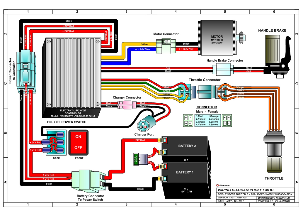
Razor Pocket Mod Bistro Electric Scooter Parts Electricscooterparts Com

Amazon Com 24v Control Module 7 Connectors 6 Pin Throttle Model Hb2430 Tyd6k Fs Rohs Fit For Razor Ground Force Drifter V3 Crazy Cart V1 4 Dune Buggy V12 Razor Ground Force Go Kart V13 Automotive

45 Hp Mariner Outboard Which Wires Go To Switch Box From Trigger Plate